RETURN TO MAIN PAGE
DISCUSS in the FORUM
English version
German version
Notes
|
|
Messerschmitt Me. 109
Handling and Manoeuvrability Tests
BY
M. B. MORGAN,
M.A. and D. E. MORRIS,
B.SC.
COMMUNICATED BY THE PRINCIPAL DIRECTOR OF
SCIENTIFIC RESEARC (AIR)
MINISTRY OF SUPPLY
__________________________________
Reports and Memoranda No. 2361
September 1940*
|
Summary. – Reasons for Enquiry. – Comprehensive handling and manceuvrability tests were required on the
Me. 109, for comparison with similar tests already made on other modem
single-seater ghter6,7,8,9. The performance of a captured Me. 109 was
measured in France, and the aircraft then flown to England for these further
tests.
Range of Investigation. – The handling tests covered the following ground : – ease of
take-off and landing ; trim and stability ; " one control " tests,
flat turns and sideslips ; stalling tests, including a determination of CLmax
; high-speed dive ; harmony and "
feel " of the controls. An
investigation of the fighting qualities of the Me. 109 included dog fights
with Hurricanes and Spitfires, measurement of aileron forces and times to
bank at speeds up to 400 m.p.h., and an analysis of the turning performance
of the aircraft. Pilots' views on cockpit layout, comfort and
view are given in an Appendix to the report.
Conclusions. – (i) Take-off is fairly
straightforward. Landing is difficult until the pilot gets used to the
aircraft.
Longitudinally the aircraft is too stable for a fighter. There is a
large change of directional trim with speed. No rudder trimmer is fitted ;
lack of this is severely felt at high speeds, and limits a pilot's ability to
turn left when diving. Fin area
and dihedral are adequate. The stall is not violent, and there is no
subsequent tendency to spin. CLmax is 1.4, flaps up and 1.9, flaps down. No
vibration or " snaking " develop in a high-speed dive. Aileron
snatching occurs as the slots open. All three controls are far too heavy at
high speeds. Aerobatics are difficult. (ii) The
Me. 109 is inferior as a fighter to the Hurricane or Spitfire. Its
manoeuvrability at high airspeeds is seriously curtailed by the heaviness of
the controls, while its high wing loading causes it to stall readily under
high normal accelerations and results in a poor turning circle. At 400
m.p.h. a pilot, exerting all his strength, can only apply 115 aileron,
thereby banking 45 deg. in about 4 secs. From the results Kb, for the Me. 109
ailerons was estimated to be - 0.145. The
minimum radius of turn without height loss at 12,000 ft., full throttle, is
calculated as 885 ft. on the Me. 109 compared with 696 ft. on the Spitfire. The
cockpit is too cramped for comfort. |
|
1. Introduction. – The Messerschmitt Me. 109 single
seater fighter has, since the outbreak of war, been the most extensively used
fighter type of the German Air Force, and corresponds roughly to our
Hurricane or Spitfire.
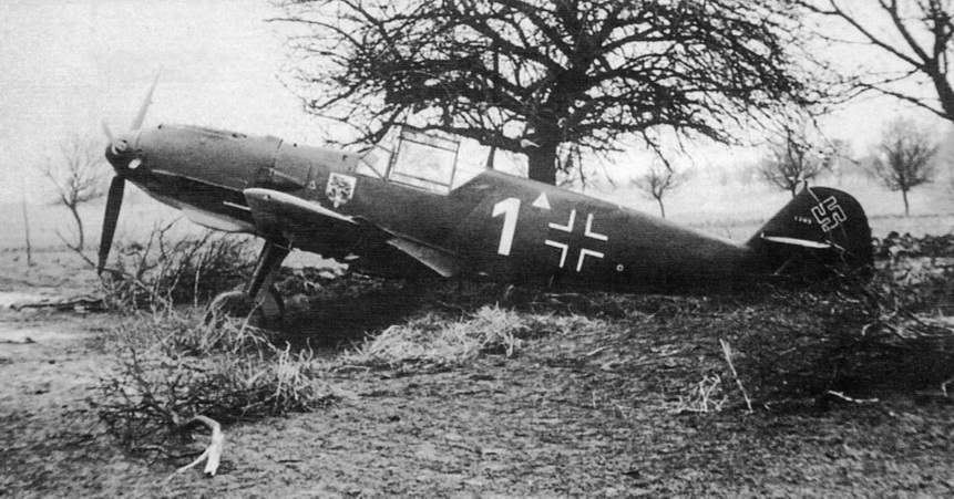
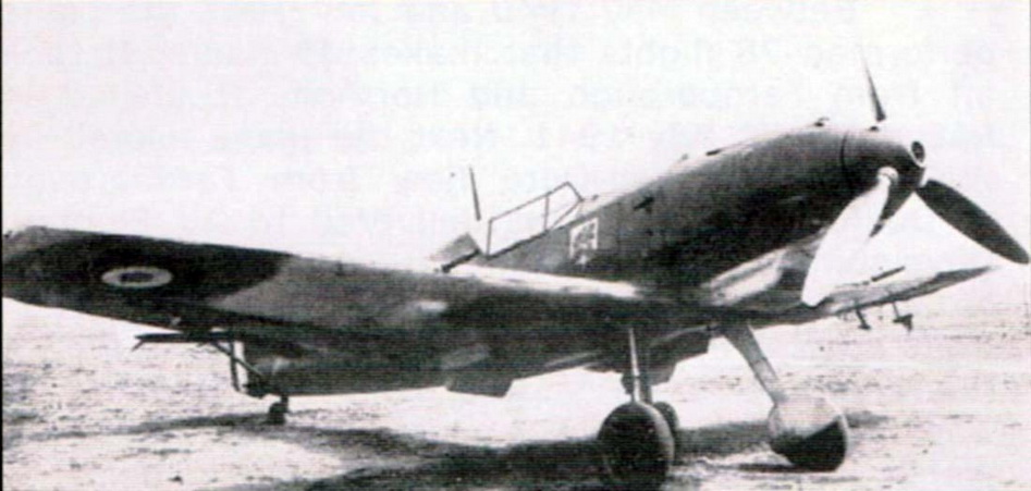
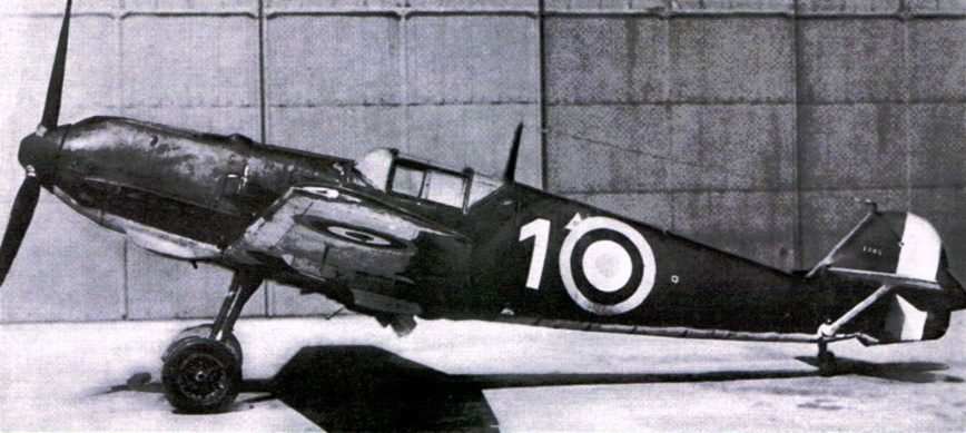
A number of crashed Me.109E fell into French hands at various times,
and two aircraft were captured intact. Examination of these aircraft enabled
the Aeronautical Technical Service of the French Air Ministry to prepare a
very thorough descriptive report1. In addition, performance tests
were made, and the flying qualities of the aircraft were briefly examined;
the results of the flight tests are contained in two further French reports2,3
.
One of the aircraft was crashed during the performance tests, and the
work was completed on the other. This second aircraft was then flown to
England. After several weeks at the A. & A.E.E., Boscombe Down4,
it arrived at the Royal Aircraft Establishment for a comprehensive
investigation of its handling qualities. The results of this investigation
form the subject of the present report. * R.A.E. Report No. B.A. 1640 received 18th January, 1941. The aircraft was available for flight
tests at the R.A.E. during May and June, 1940. It was flown by all three
pilots of the Aerodynamic Flight, the total flying time being 35 hours. 2. Description of the
Aircraft. – 2.1. History. – Since the Me. 109 first appeared the design has
undergone a number of major modifications. The following are believed to be
the main stages in the development of the aircraft to its present form ; the
list of types is that given in the French descriptive report1, and
is not an official German classification. Type 1. – The first version (1938) had a 670 b.h.p. Jumo
210 engine, fixed-pitch wooden airscrew, and two nose machine guns firing through
the airscrew disc. Type 2. – In the second version the Jumo 210 engine was
retained, but a twin-bladed variable-pitch airscrew was fitted, and four
machine guns were carried, two in the nose and one in each wing. Type 3 (a). – A much more powerful engine was next installed,
the Jumo 210 being replaced by a 1,100 b.h.p. direct injection D.B.601
driving a three-bladed variable pitch airscrew. The wing structure was
considerably stiffened up, and about 60 lb. of permanent ballast was inserted
in the rear of the fuselage to get the C.G. back. Four machine guns were
still carried. Type 3 (b). – This version only differs from type 3 (a) in that
the wing armament consists of two 20 mm. cannon instead of the two machine
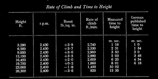
guns. The aircraft tested at the R.A.E. was of type 3 (b). 2.2. Performance. – As a matter of interest a summary of
the performance results obtained during the French tests2 is included below.
The weight of the aircraft during these tests was 5,600 lb. It is stated in
the French report that the speeds quoted depend on an estimate of the
position error curve, and that in consequence there might be an inaccuracy of
2 to 3 percent on speed, i.e. +/- 9 m.p.h. on top speed. Top level speed 355 m.p.h. at 16,400 ft., 2,400
r.p.m. + 2 3 lb./sq. in. boost pressure. Radiators closed. 330 m.p.h. at 14,800 ft., 2,400
r.p.m. + 2 1 lb./sq. in. boost pressure. Radiators open. |
|
Owing to cooling difficulties the radiators were open up to
13,000 ft. and then gradually closed up to 26,000 ft. This may account for
the discrepancy between the measured times to height and those published in Germany.
The top level speed agreed well with the published figure. Absolute ceiling.
– 32.000 ft. |
|
2.3.
General. – The
aircraft is a low-wing monoplane of fairly clean design. A list of
aerodynamic data is given in Table 1, a three view general arrangement
drawing in Fig. 1, while photographs of the aeroplane are reproduced in Fig.
2. The cockpit layout is shown in Fig. 3, and a photograph of the windscreen
is given in Fig. 4. In size, the aircraft is smaller than the Hurricane and
Spitfire, and the wing loading is highabout 32 lb./sq. ft. compared with the
25 lb./sq. ft. of the Hurricane and Spitfire. From landing considerations the
designer has thus found it expedient to incorporate high lift devices, and
the aircraft is equipped with slots, slotted flaps and slotted ailerons which
come down 10 deg. when the flaps are lowered ; the ground attitude has been
made large, 17 deg. at the wing root, in order to utilise a large proportion
of the available CLmax. The structure is fully described in Ref.
1. The aircraft is of all metal construction except for the movable control
surfaces and the flaps; these are fabric covered. The general standard of
surface finish is good, the entire metal covering being flush riveted.
Throughout the design it is obvious that great attention has been paid to
ease of maintenance and inspection, and care has been taken to ensure that
damaged components can be readily and quickly replaced by new parts. During the R.A.E. tests the aircraft
was flown with tanks full at its full service load. Ballast weights .were
added at the appropriate places in lieu of equipment which had been removed
(ammunition, wireless, etc.), so the C.G. position should also be
representative. The all-up weight was 5,580 lb. with the C.G. 24.8 in. aft of
the leading edge at the root (h =
0.302). This loading agrees well with the value of 5,600 lb. quoted for the
all-up weight by the Germans. 2.4.
Engine. – The engine is
a 1,100 b.h.p. direct injection D.B.601. This is a 12-cylinder 60-deg.
inverted V liquid-cooled engine with spar reduction gear. Provision is made
to instau a cannon firing along the axis of the reduction gear through the
airscrew hub, but the French have no evidence that the Me.109 has yet been
equipped in this way. Bosch injection pumps are used to meter the fuel. The
engine is glycol cooled. There are two radiators, one under each wing near
the trailing edge. Each radiator is provided with a flap, operated from a
wheel in the cockpit, which enables the cooling to be regulated. An oil
cooler is carried in a duct underneath the fuselage. The air intake to the
supercharger is from a scoop protruding from the engine cowling on the left
side of the aircraft. An interesting feature is that the supercharger is
driven through a hydraulic coupling; the advantages of such a system are
discussed in Ref. 1. 2.5.
Airscrew. – A 10.2-ft.
diameter three-blade variable-pitch metal airscrew is fitted. It is of V.D.M.
design, the pitch being controlled electrically. This type of airscrew is
used very widely on German military aircraft. The pilot can set the pitch at
any value between 22.5 deg. and 90 deg., i.e. the airscrew is fully
feathering. A stationary electric motor fixed to the crankcase just behind
the airscrew hub is used to alter the blade setting through a flexible drive
and a differential reduction gear. A pitch indicator is provided in the
cockpit ; this is coupled mechanically to the electric motor, and takes-the
form of a clock face with hour and minute hands, about ten minutes on this
" clock " being equivalent to 1 deg. change of pitch. There is no
provision for overning the r.p.m. and the pilot must set the pitch to give
the r.p.m. desired for any condition of flight. 2.6.
Fuselage. – A drawing of
the fuselage, including a number of cross-sections, is given in Fig. 5. There
is only a very small fillet at the wing-body junction, and the side of the
fuselage is roughly normal to the upper surface of the wing. The under
surface of the fuselage remains flat, flush with the under surface of the wing,
for more than 3 ft. to the rear of the trailing edge ; the fuselage
cross-section then gradually assumes an ovoid form, and finally becomes pear
shaped near the tail unit, the fin being merged very gradually into the
fuselage.
About 60 lb. of permanent ballast carried at the rear of the fuselage;
this had to be installed because of the added weight forward when changing
from the Jumo 210 to the D.B. 601 engine. The undercarriage is attached to
the fuselage at the wing root, and retracts sideways into the wings. The
aircraft can thus be left standing on its undercarriage when the wings are
removed, a useful maintenance feature. 2.7.
Wings. – 2.71. Wing Form. – In plan the
wings have a straight taper, with a sweepback of 1 deg. at the quarter-chord line. The
wing tips are fairly square cut, and the ratio root chordltip chord is
2.06 1.
The thickness/chord ratio is 0.148 at the root and 0.105 at the tip;
all along the span the aerofoil section has a 2 per cent. camber with the
maximum thickness at about 30 per cent. of the chord, so the root and tip
sections resemble NACA 2315 and 2310 respectively. There is no wing twist.
The dihedral angle, 5.75 deg., is fairly high.
The surface finish is good; the metal skin is flush riveted and all
inspection doors, etc., are flush and well fitting when closed. 2.72.
Slots. – The slots
occupy 46.2 per cent of the span and extend well inboard of the ailerons ( F
. l). Sections of the wing with slat open and closed are given in Fig. 6. The
slat is articulated to two transmission rods which run straight out of the
wing and are linked together by a robust system of rigid rods and bell-crank
levers; it opens and closes very freely, and when closed the fit between wing
and slat is very good. A surprising feature is the absence of any form of
damping device in the mechanism. The slat chord and gap are considerably
smaller than those suggested in A.D.M. 253 for the guidance of British
designers. 2.73.
Flaps. – The 25 per
cent. c slotted flaps are fairly large, occupying 51.8 per cent. of the wing
span. The ratio flap arealgross wing area is 0.14, and the maximum angle is
42½ deg. A plan and sections of the flap are given in Fig. 7. An interesting
point is that the portion of the slotted flap immediately behind the wing
radiator is thickened in section, as shown in Fig. 7. This is probably done
to prevent the radiator flap stalling when fully open at low climbing speeds
; it will be seen that the bulge on the flap considerably reduces the very
large expansion at the rear of the radiator duct with radiator flap open. The
slotted flaps are operated mechanically from a 11.7-in. diameter wheel on the
pilot's left; four complete turns are required to fully lower the flaps. They may be set in any interrnediate
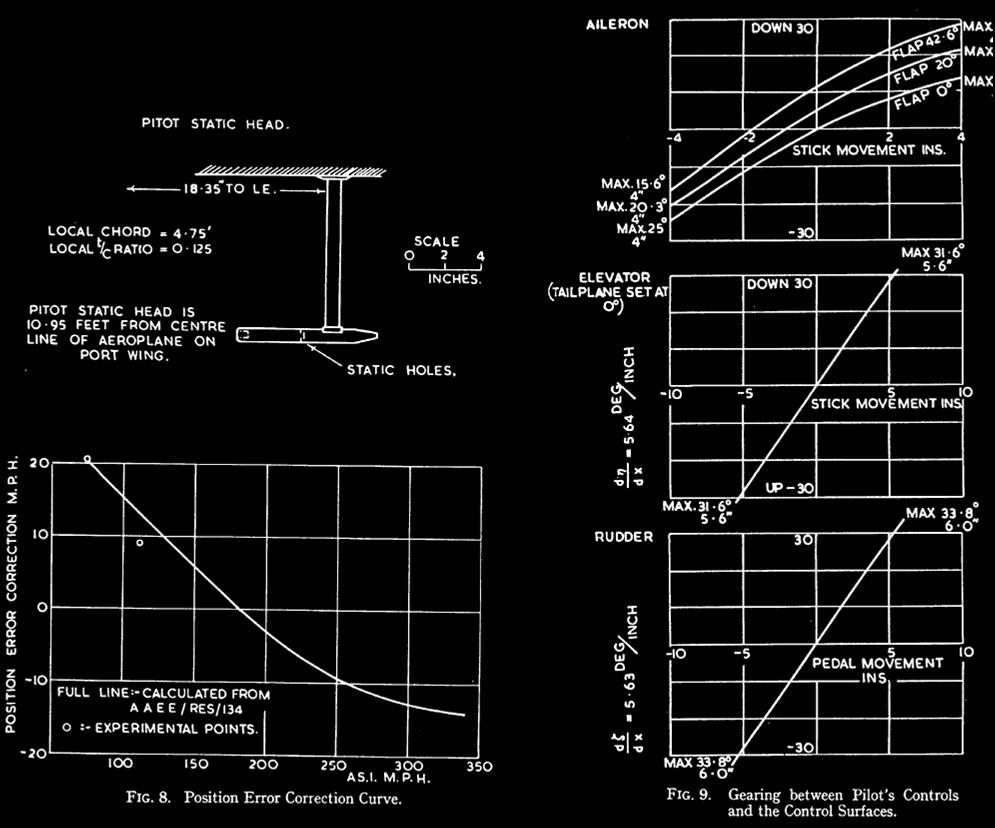
angle. 2.74.
Pitot-static Head and Estimated
Position Error. – A drawing of the pitot-static head is given in Fig. 8.
It is situated underneath the port wing at 0.68s, and in terms of the local wing chord is 0.32c from the local leading edge and
0.155c below the under surface of
the wing.
For some of the tests (trim curves and aileron forces) it was
desirable to convert pilots' A.S.I. to indicated airspeed so that CL
could be deduced. Accordingly the position-error correction curve was estimated
from A. & A.E.E. generalised curves5; the estimated position
error curve is plotted in Fig. 8. S 2.8.
Control Surfaces. – The relations between movements of the top of the stick or
centre of a rudder pedal, in inches, and the corresponding angular movements
of the appropriate control surface are illustrated in Fig. 9. When tested on
the ground all three controls showed remarkably little friction and no
appreciable backlash. Each control surface is mass-balanced, and even the
control column is statically balanced for fore-and-aft movement by means of a
counterweight incorporated in the elevator control circuit. Transmission
between the cockpit controls and the control surfaces is by a mixed system of
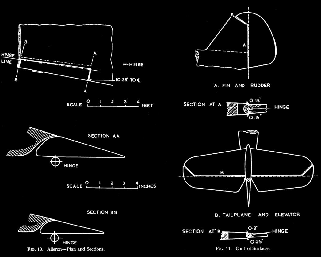
rods and wires. 2.81.
Ailerons. – Drawings of
the slotted ailerons are given in Fig. 10. It will be seen from the sections
that the slot width is very small. The ailerons have a 21.6 per cent. balance
and the hinge position is well below the under surface. Each aileron has a
mass balance weight of streamlined form carried on an arm projecting
downwards; an aileron was removed and it was found that its centre of gravity
coincided with the hinge line, i.e. complete static mass balance is achieved.
When the flaps are up the ailerons have a droop of 1.2 deg. and a 2:l
differential (maximum angles 13.5 deg. down and 25 deg. up). As the flaps are
lowered both ailerons come down progressively, and when the flaps are fully
lowered (42.5 deg.) both ailerons come down 11 deg.; the differential is now
slightly less. Fig. 9 shows the aileron-stick gearings for three flap
settings (0 deg., 20 deg. and 420 5 deg.).
A small fixed trimming tab is attached to each aileron (Fig. 10).
These tabs are of metal sheet, and can be bent when on the ground to adjust
lateral trim. 2.82.
Tail Unit. – Drawings of the fin and rudder, including sections are
given in Fig. lla, and similar drawings are given for the tailplane and
elevator in Fig. llb. Both these controls are horn balanced; the percentage
balance is 10.35 per cent. for the elevator and 8.5 per cent. for the rudder.
The mass-balance weights are carried in the horns, and it is believed that
static mass balance is achieved in each case.
The tailplane is high; a large portion of the rudder comes below it,
and thus remains unshielded at high incidences, a useful anti-spin feature.
No rudder trimmer is provided which can be operated in flight. When on
the ground directional trim may be adjusted by bending a portion of the
trailing edge of the rudder.
Longitudinal trimming is effected by means of an adjustable tailplane
having a 12 deg. incidence range and operated mechanically from a handwheel
on the pilot's left; this wheel is mounted concentrically with the
flap-actuating wheel, and by winding both wheels together the pilot
automatically compensates for the change of trim due to flaps. 3.
Programme of Tests. – A number of
modern aircraft have been put through a standard series of handling tests at
the R.A.E. The aircraft tested have included such single-seater fighters as
the Spitfire6, Hurricane7, Gloster F5/348
and Curtiss H-759. As a first step it was thus thought of
comparative value to put the h1e.109 through the same series of tests, which
covered the following points ;-pilots' impressions of ease of tike-off and
landing ; longitudinal and directional trim ; control with rudder and
ailerons alternately held fixed, flat turns and sideslips; behaviour at and
near the stall (ADM 293 – issue 2) ; harmony and " feel " of the
controls.
In addition to the above standard programme, CLmax was
determined with a trailing static, and the behaviour in a high-speed dive was
investigated. Rough measurements were also made of aileron stick forces and
rates of roll, for comparison with the results of similar aileron tests9
on the Spitfire, Gloster F5134 and Curtiss H-75.
The fighting qualities of the aircraft were next examined by staging a
series of dog fights and diving attacks between the Me. 109 and a Spitfire,
both flown by pilots of the Aerodynamic Flight. Later a number of service
pilots who had recently seen active service were invited to the R.A.E. with
their Spitfires and Hurricanes in order to practice aerial combat against the
Me.109. Information of considerable interest was gained from these mock
fights.
Finally the R.A.E. pilots were asked to give their opinions on cockpit
layout, comfort, view, etc. ; these are summarised in Appendix I at the end
of the report. 4. Handling Tests. – 4.1. Take-off and landing. – 4.11. Take-of. – All the
take-off tests were done with the slotted flaps set at the recommended
position of 20 deg. The throttle can be opened very- quickly, for as the
engine is of the direct injection type it responds almost instantaneously to
throttle movement without choking. . The initial acceleration is very good,
and there is no tendency to swing or bucket; during the ground run
theaircraft rocks slightly from side to side, . but this feature is not
sufficiently pronounced to worry the pilot. On opening the throttle the stick must
be held hard forward. The tail comes up fairly quickly, and the stick can
then be eased back. It is advisable for the pilot to hold the aircraft on the
ground for a short while after he feels that flying speed has been gained, as
if the aircraft is pulled off too soon the left wing will not lift, and on
applying opposite aileron the wing comes up, then falls again, with the
ailerons snatching a little. If no attempt is made to pull the aircraft off
quickly, the take-off is quite easy and straightforward. The take-off run is
remarkably short, and the initial rate of climb is exceptionally good. In
these respects the Me.109 is definitely superior to those Spitfires and
Hurricanes having two-pitch airscrews, and compares well with the Curtiss
H-75. 4.12.
Approach. – The stalling
speeds when gliding are 75 m.p.h.* with flaps and undercarriage up and 61
m.p.h. with flaps and undercarriage down. Lowering the flaps makes the
ailerons heavier and very slightly less effective, and gives rise to a fairly
large nose-down pitching moment which can, however, be readily corrected
owing to the juxtaposition of the flap and tailplane adjustment operating
wheels ; the attitude of the aircraft at constant airspeed changes by about
10 deg. when the flaps are put down. Lowering the undercarriage causes only
very slight nose-heaviness. If the engine is opened up when the
flaps are down, as for a mislanding in which the pilot decides to go round
again, the aircraft becomes slightly tail heavy, but can easily be held with
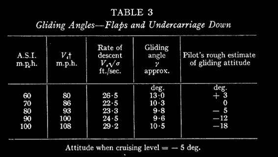
one hand while trim is adjusted. The effect of varying the approach speed on
rate of descent was measured when gliding with flaps and undercarriage down.
The results are given in the following table.
|
|
Approaching with flaps and undercarriage down the pilot has an impression
of sinking at speeds below 80 m.p.h. and of diving at speeds above 100 m.p.h.
The normal approach speed is about 90 m.p.h.
Gliding at 90 m.p.h. with flaps and undercarriage down the glide path
is fairly steep and the view is reasonably good owing to the nose-down
attitude of the aircraft. Longitudinally the aircraft is markedly stable,
stick free, and the elevator is heavier and more responsive at this speed
than is usual on single-seater fighters, comparing well with that of the
Curtiss H-759; these
features add considerably to the ease of the approach. Lowering the ailerons
11 deg. with the flaps detracts little from their effectiveness, but makes
them feel much heavier; the rudder is
rather sluggish for small movements.
Normal gliding turns can be made at 90 m.p.h. flaps down, without any
signs of stalling or undue loss of height. * Throughout this report speeds
quoted are pilots' A.S.I. unless otherwise stated. t Position error estimated from
A.A.E.E. generalised curves as described in 5 2.74. 4.13. Landing. – This is
definitely more difficult than on the Hurricane or Spitfire, mainly owing to the high ground attitude of the
aircraft. The aircraft must be rotated through a large angle before touch
down, and this requires a fair amount of skill on the part of the pilot, and
tempts him to do a wheel landing. If a wheel landing is made thereis a strong
tendency for the left wing to drop just before touch-down, and when the
ailerons are used quickly to bring the wing up they snatch a little, causing
the pilot to over-correct. By holding off a little high the aircraft can be
made to sink slowly to the ground on all three wheels, and there is then no
tendency for a wing to drop. A pilot quickly becomes accustomed to the
landing technique required on this aircraft, and should have no difficulty
after a few practice landings.
The centre of gravity is unusually far behind the main wheels, and the
brakes can be applied fully immediately after touch-down without fear of
lifting the tail. The ground run is very short, and there is no tendency to
swing or bucket. Owing to the large ground attitude, and the consequent high
position of the nose, the view ahead during the hold-off and ground run is
extremely bad. Landing at night would probably be difficult. 4.14. Ground Handling. – Because of
the large weight on the tail the aircraft can be taxied very fast without
bouncing or bucketing, but is difficult to turn quickly; an unusually large
amount of throttle is necessary, in conjunction with harsh use of the
differential brakes, when manoeuvring in a confined space. Apart from turning
performance, the ground handling qualities are good. The brakes are powerful
and can be used harshly without lifting the tail; they are foot operated, and
the pilots expressed a strong preference for the hand-operated system
universal on British aircraft. 4.2.
Trim. – 4.21. Lateral. – A small fixed tab is fitted to each
aileron ; these tabs can be adjusted when on the ground to correct any
tendency to fly one wing low. No means are provided for trimming the ailerons
in flight.
There is no pronounced change of lateral trim with speed or throttle
setting if care is taken to fly without sideslip. As no trimmer is fitted to
the rudder, a small amount of sideslip is quite probable, particularly at
high speeds when the rudder is fairly heavy; owing to the large wing dihedral
any such inadvertent sideslip gives rise to a pronounced rolling moment,
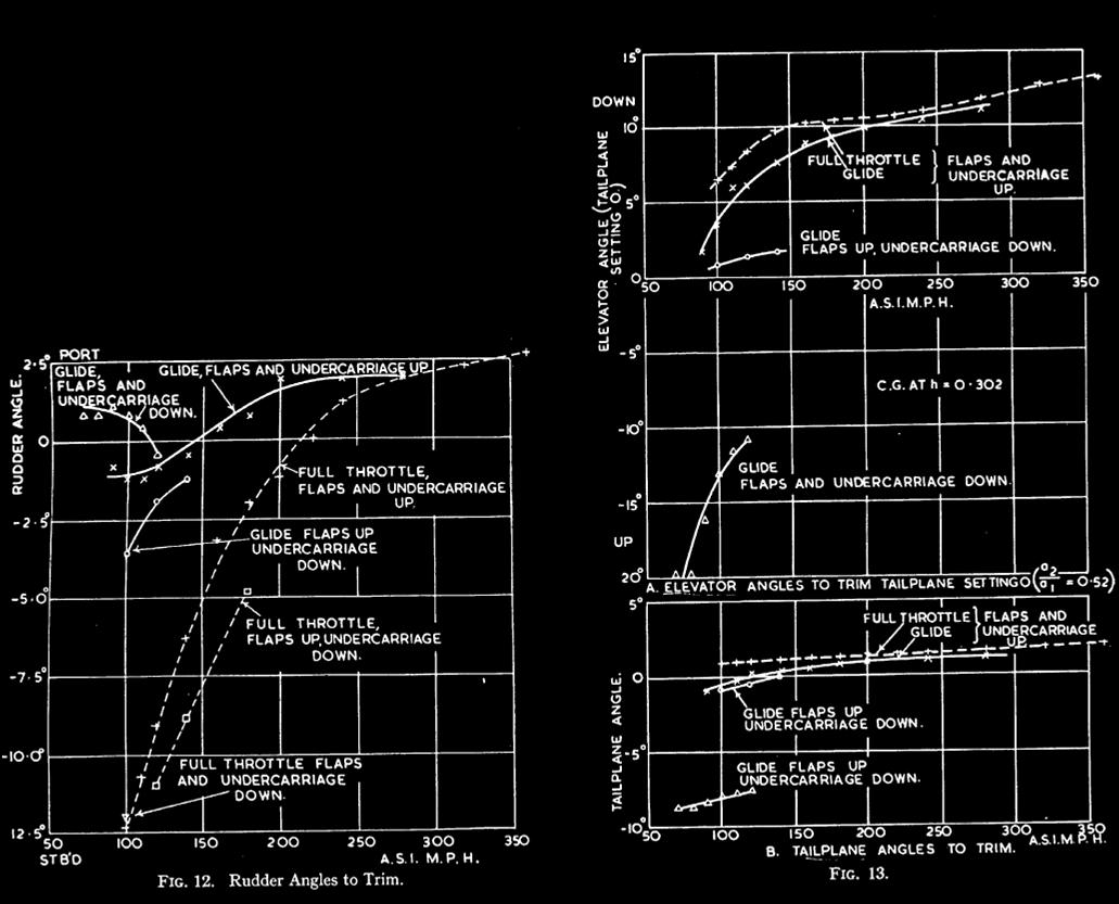
necessitating use of the ailerons for its correction. 4.22.
Directional. – The absence of a rudder trimmer is a bad
feature, since there is a large change of directional trim with speed. A
rudder angle indicator was fitted, and rudder angles necessary to fly
straight and level with no sideslip were measured at various speeds when
gliding and at full throttle, with flaps and undercarriage in turn up and
down. The resulting curves of rudder angle to trim plotted against pilot's
A.S.I. are given in Fig. 12. It will be seen that when flying at full
throttle there is a very rapid variation of directional trim with speed. The
practical consequences are not quite as alarming as the curves might suggest,
because the rudder is light at low speeds, and very little force is needed to
hold on the 5 deg. of right rudder necessary when climbing at 150 m.p.h. ;
the French report2 that it is difficult to turn to the right when climbing
was not confirmed, and is thought to be misleading; on the aeroplane tested
at the R.A.E. climbing turns could be done with equal facility to both left
and right.
It is at high speeds that lack of a rudder trimmer most seriously
inconveniences the pilot. At 215 m.p.h. the aircraft is trimmed
directionally, no rudder being required. At higher speeds left rudder must be
applied, and at 300 m.p.h. about 2 deg. of left rudder are needed. The rudder
is very heavy at high speeds, and a large force is necessary to apply even
such a small amount; this becomes very tiring, and affects the pilot's
ability to put on more left rudder to assist a turn to the left. Consequently
at high speeds the Me.109 turns more readily to the right than to the left. 4.23.
Longitudinal. – The adjustable tailplane is controlled from a
11.7-in. diameter wheel on the pilot's left (Fig. 3) ; 5.75 turns are
required to move the tailplane through its full angular range (+ 3.4 deg. to
- 8.4 deg.) and the wheel rotation is in the natural sense, i.e. winding
forward pushes the nose of the aircraft down.
Tailplane angles to trim were measured at various speeds when gliding
with (i) flaps and undercarriage up, (ii) flaps up and undercamage down,
(iii) flaps and undercaniage down and at full throttle with flaps and
undercarriage up. The centre of gravity was at h = 0.302 with
undercaniage down ; raising the undercarriage has little effect on the
fore-and-aft C.G. position as wheels retract sideways.
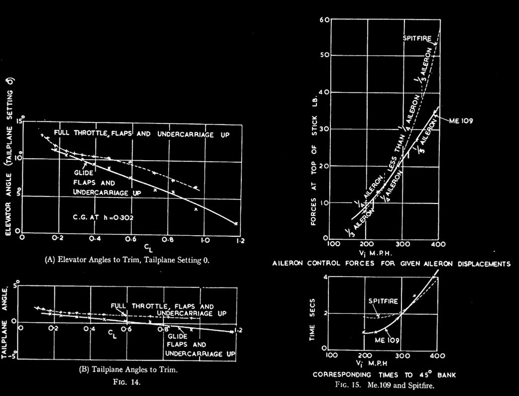
The curves so obtained are given in Fig. 13b, where tailplane angles
to trim are plotted against A.S.I. For ease of interpretation in terms of
stick-free stability some of the curves are replotted against CL in Fig. 14b
; the estimated position error curve of Fig. 8 was used in obtaining CL
from pilots' A.S.I.
During the measurement of tailplane angles to trim, simultaneous
readings were taken of the corresponding elevator angles (from a
stick-position indicator). The measured elevator angles were thus obtained
with the tailplane setting varying, whereas, in order to obtain a picture of
the stick-fixed stability of the aircraft, elevator angles to trim with the
tailplane at a constant setting are necessary. By estimating the ratio of the
change in tail lift per degree elevator movement to that per degree tailplane
movement (a,/ad it is possible to convert the measured elevator angles to
those corresponding to a fixed tailplane setting. This has been done and the
resultant elevator angles to trim tailplane fixed, are plotted against A.S.
I. in Fig. 13a, and some of the curves are replotted against CL in
Fig. 14a.
The nose-down change of trim due to lowering the flaps and undercamage
is large, but readily corrected. It will be seen that the aircraft is very
stable when gliding at low speeds with flaps down, while Fig. 14 shows that
the stability of the aircraft with flaps and undercarriage up is greater than
is customary on single seater fighters ; this curtails manoeuvrability in the
looping plane, and contributes to the heavy " feel " of the
elevator, particularly at high speeds. Fig. 14 also shows that slipstream
does not cause a large change of trim, flaps up, and only slightly decreases
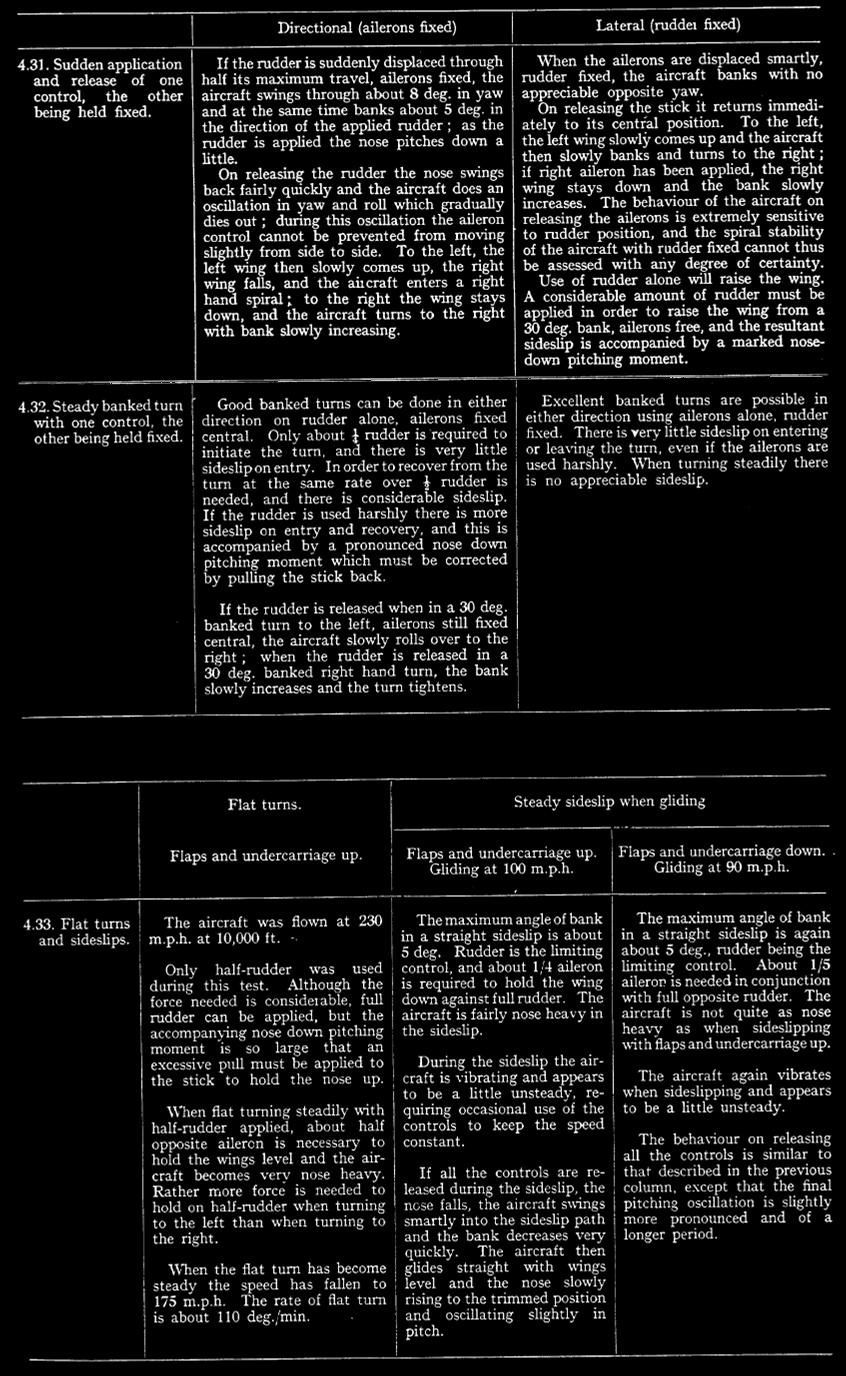
the stability. 4.3.
" One Control " Tests, Fat Turns and Sideslips. – This group
of tests is designed to provide information for assessing the relative
degrees of static directional stability ( Nv ) and lateral
stability (Lv.).
The aircraft was trimmed longitudinally to fly straight and level at
230 m.p.h. at 10,000 ft., 2,200 r.p.m. At 230 m.p.h. under these conditions
the aircraft is not in trim directionally, and a slight pressure is required
on the left rudder bar to keep the aircraft flying straight with no sideslip;
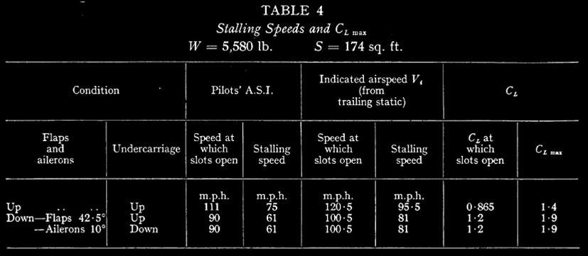
this should be borne in mind when considering the results given below. 4.4. Stalling Tests. – 4.4 1. Determination
of CL max – The aircraft was fitted with a
swivelling pitot head and a suspended static head (60-ft. cable) in order to
measure the indicated airspeed at and near the stall. Only one flight was
made, as operating a suspended static head from a single-seater aircraft with
a rather cramped cockpit is difficult. Stalling speeds with engine throttled
right back were measured with flaps and undercarriage up and down, and the
speed at which the slots opened were also noted ; in every case both slots
opened almost simultaneously.
The following results were obtained : - |
|
4.4. Stalling Tests. – 4.4 1. Determination
of CL max – The aircraft was fitted with a swivelling
pitot head and a suspended static head (60-ft. cable) in order to measure the
indicated airspeed at and near the stall. Only one flight was made, as
operating a suspended static head from a single-seater aircraft with a rather
cramped cockpit is difficult. Stalling speeds with engine throttled right
back were measured with flaps and undercarriage up and down, and the speed at
which the slots opened were also noted ; in every case both slots opened
almost simultaneously. The following
results were obtained : - |
|
Lowering the
slotted flaps 42.5 deg. and the slotted ailerons 10 deg. thus increases CL
max by 0.5. This is roughly the value to be expected from normally
designed slotted flaps and ailerons arranged as on the Me.109, but is somewhat
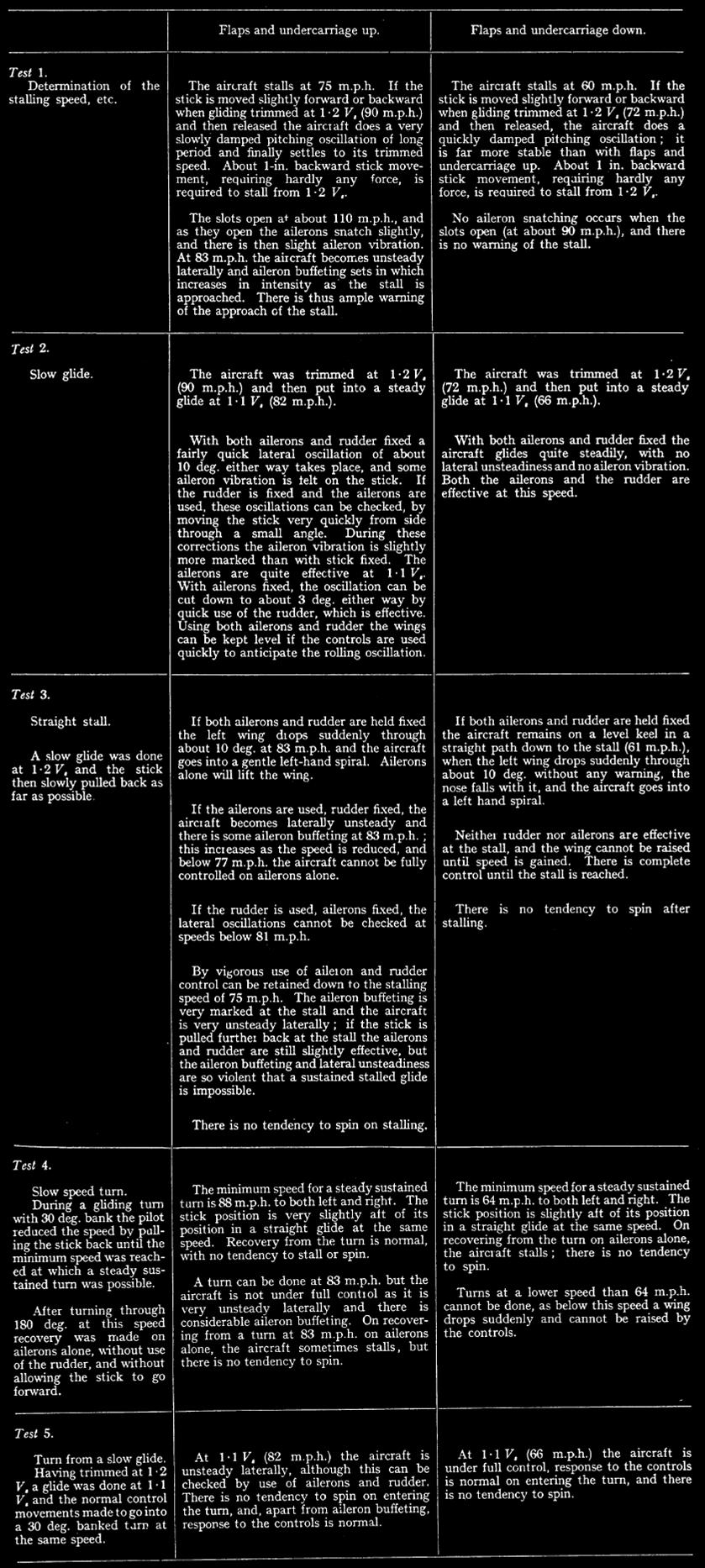
less than that attainable with efficiently designed modem slotted flaps. 4.42. ADM. 293 – issue 2. – The aircraft
was subjected to the tests laid down in ADM. 293 – issue 2. The all-up weight
was 5,580 lb. with the C.G. at h = 0.302. The results obtained are
given in the follo\ving tables ; speeds quoted are pilots' A. S. I. |
|
4.5. High-Speed
Dive. – The aircraft was dived at 370 m.p.h. and all three controls were in turn
given a slight displacement and then released. No vibration, flutter or
" snaking " developed. If the elevator is trimmed for level
flight at full throttle, a moderately large push is necessary to hold the
aircraft in the dive, and there is a temptation to wind the trimmer forward.
If this is done, recovery is very difficult unless the trimmer is first wound
back again, owing to the excessive heaviness of the elevator at high speeds. At 370 m.p.h. a considerable amount of
pressure is needed on the left rudder bar to hold the aircraft straight, and
if the rudder is displaced in either direction and released, the aircraft
eventually banks and turns to the right. Small rudder displacements,
sufficient to yaw the nose about 10 deg., give rise to no appreciable
nose-down pitching moment. Large rudder displace-ments do cause the nose to
pitch down, but as the rudder is very heavy at 370 m.p.h. they would not
normally be used. 4.6. Flying
Controls. – 4.61. Ailerons. – At low speeds the aileron
control is very good, being similar to that of the Curtiss H-75 ; there is a
positive " feel ", there being a definite resistance to stick movement, and response
is brisk. In these respects the Me.109 ailerons are better than those of the
Spitfire, which become so light at low speeds that they lose all " feel
". As the speed is increased the ailerons
gradually become heavier, but response remains excellent. They are at their
best between 150 m.p.h. and 200 m.p.h., and are described as " an ideal
control " over this speed range. Above 200 m.p.h. they start becoming
unpleasantly heavy, and at 300 m.p.h. are far too heavy for comfortable
manoeuvring. Between 300 m.p.h. and 400 m.p.h. the ailerons are described as
" solid " ; at 400 m.p.h. a pilot, exerting all his strength,
cannot apply more than about fifth-aileron. More detailed aileron tests (measurement
of stick forces and time to bank) were-made, and are described in section
5.2. These tests showed that, although the Me.109 ailerons felt much heavier than those of
the Spitfire at speeds between 300 m.p.h. and 400 m.p.h., the aircraft could
be made to bank at about the same rate as the Spitfire at these high
airspeeds. The more " solid " feel of the Me.109
ailerons at high airspeeds is attributed to smaller stick travel (+/- 4 in.
compared with +/- 8 in. on the Spitfire)., fairly rigid control circuit, and
partly to the awkward seating position of the pilot. The matter is more fully
discussed in section 5.2. Throttling back the engine does not alter
the effectiveness of the ailerons at any speed. Lowering the flaps at low
speeds (the ailerons come down 11 deg. with the flaps) makes the ailerons
considerably heavier and slightly reduces their effectiveness, although
response is. still amply adequate. Apart from their excessive heaviness at high
speeds, the most serious defect of the Me.109 ailerons is a tendency to
snatch as the wing tip slots open. This is particularly noticeable when
manaeuvring. For example, if the stick is pulled back in a tight turn,
putting additional g on the aircraft, the slots open at quite a high airspeed
; as they open, the stick suddenly snatches laterally
through several inches either way, sufficiently to upset a pilot's aim in a
dog fight. The snatch appears to be associated with
the opening of the slots, for once they are fully open a steady turn can be
done, with no aileron vibration, until the stall is approached. As mentioned in section 4.42 (ADM. 293)
some aileron snatching also occurs when gliding near the stall with flaps up
and slots open; it disappears on lowering the flaps fully, and so does not
worry the pilot during the approach glide. 4.62. Elevator.
– The elevator is an exceptionally good control at low speeds ; it is
fairly heavy, and is not over sensitive during the approach glide, while
response is excellent. Throughout the speed range the elevator is heavier
than that of the Hurricane or Spitfire, but up to 250 m.p.h. this is not
objected to, since it is very responsive. Above 250 m.p.h. the elevator
becomes definitely
too heavy for comfort, and between 300 m.p.h. and 400 m.p.h. is so heavy that
maneuvrability in the looping plane is seriously restricted; when diving at
400 m.p.h. a pilot, pulling with all his strength, cannot put on enough g to
black himself out if trimmed in the dive. At low speeds the elevator is slightly
lighter when the engine is throttled back, and is very slightly less
responsive. The elevator control is unaffected by lowering the flaps. 4.63. Rudder. – The rudder
is light but rather sluggish at low speeds, and large displacements are
required for quick response. As the speed is increased the range of
sluggishness decreases, and at 200
m.p.h. has disappeared, the rudder now being effective for small
displacements and still quite light. Between 200 m.p.h. and 300 m.p.h. the
rudder is the lightest of the controls for small movements, assisting
directional aim for gunnery ; but at 300 m.p.h. the absence of a directional
trimmer is severely felt, as a small amount of left rudder is necessary to
fly without sideslip, and
the force required, although not excessive, becomes very tiring. As the speed
is increased to 400 m.p.h. the rudder becomes extremely heavy, and at 400
m.p.h. only small displacements can be made; and the force required to hold
the aircraft straight is considerable. Throttling back the engine at low speeds
makes the rudder a little more sluggish, and lowering the flaps further
reduces the rudder effectiveness, although response is still adequate when
large displacements
are used. If the speed is increased when gliding with flaps down, the rudder
starts juddering slightly at 100 m.p.h. ; this juddering increases rapidly as
the speed is increased, and at 120 m.p.h. is so pronounced that any further
increase of speed is inadvisable. As the normal approach speed with flaps
down is 90 m.p.h., this rudder vibration is not normally noticed, and is of
little practical importance. 4.64.
Harmony. – The controls are fairly well harmonised between 150 m.p.h. and 250
m.p.h., although the elevator is somewhat heavy compared with the ailerons
and rudder. At low speeds harmony is spoiled by the sluggishness of the
rudder, while at high speeds harmony is poor because of the excessive heaviness
of the ailerons. 4.65.
General. - Features particularly liked by the pilots were the positive "
feel " of the ailerons and elevator at low speeds, and the excellent
response characteristics of all three controls at medium speeds. The control
characteristics which were particularly complained of, and which were
considered to spoil the aircraft as a fighter, were – (i) The undue
stiffening up of the controls, particularly the ailerons, at high speeds. (ii) The
aileron snatching caused by the slots opening during manoeuvres, and (iii) The
absence of a rudder trimmer. 4.7.
Aerobatics. – Aerobatics are not easy on this aircraft. Loops must be started from
about 280 m.p.h., when the elevator is unduly heavy; there is a marked
tendency for the slots to open near the top of the loop, resulting in aileron
snatching and loss of direction, and in consequence accurate looping is
almost impossible. At speeds below 250 m.p.h. when the
ailerons are light and very effective, the aircraft can be rolled very quickly,
but there is a strong tendency for the nose to fall in the final stages of
the roll, and the
stick must be moved well back in order to keep the nose up. Upward rolls are difficult; the elevator
is so heavy at high speed that only a gentle pull-out from the
preliminary dive is possible, and a considerable loss of speed is thus
inevitable before the upward
rolls'can be started. 5. Fighting
Qualities of the Me. 109. – 5.1. Dog-fights with Spitfire and
Hurricane. – Mock fights were staged between the Me. 109 and
a Spitfire, both flown by pilots of the R.A.E. In addition a number of
fighter pilots, all of whom had recent experience of operational flying,
visited the R.A.E. with their Spitfires and Hurricanes in order to practice
combat with the Me.109 ; during these fights the Me.109 was flown by an
R.A.E. pilot who had completed the handling tests described earlier in this
report, and was thus thoroughly familiar with the aircraft and could be
expected to get the best out of it. A brief account of the information
provided by these fights has already been publishedlO. The following notes
summarise the results obtained. The arrangements were for the aircraft to
take off singly and meet at about 6,000 ft. The Me.109 then went ahead and
commenced to turn as tightly as possible to see if it would out-turn our own
aircraft. After doing three or four tight turns in both directions the Me.109
was put into a dive, followed by a steep climb. The aircraft then changed
position and repeated the above programme, after which the pilots engaged in
a short general fight. When doing tight turns with the Me.109
leading at speeds between 90 m.p.h. and 220 m.p.h. the Spitfires and
Hurricanes had little difficult in keeping on the tail of the Me. 109. During
these turns the amount of normal g recorded on the Me. 109 was between 2½ and
4 g. The aircraft stalled if the turn was tightened to give more than 4 g at
speeds below about 200 m.p.h. The slots opened at about ½ g before the stall,
and whilst opening caused the ailerons to snatch ; this upset the pilot's
sighting immediately and caused him to lose ground. When the slots were fully
open the aircraft could be turned quite steadily until very near the stall.
If the stick was then pulled back a little more the aircraft suddenly
shuddered, and either tended to come out of the turn or dropped its wing
further, oscillating meanwhile in pitch and roll and rapidly losing height ;
the aircraft immediately unstalled if the stick was eased forward. Even in a
very tight turn the stall was quite gentle, with no tendency for the aircraft
to suddenly flick over on to its back and spin. The Spitfires and Hurricanes
could follow the Me.109 round during the stalled turns without themselves
showing any signs of stalling. The good control near the stall during
these turns at full throttle contrasts with the results obtained from the
ADM. 293 tests (section 4.42)) for when gliding the aircraft becomes unsteady
at 10 m.p.h. above the stall. Slipstream thus appears to have a steadying
influence on the behaviour of the Me.109 near the stall. After these turns the Me.109 was put into
a steep dive at full throttle with the airscrew pitch coarsened to keep the
r.p.m. down. It was found that both the Hurricanes and the Spitfires could
keep up with the Me.109 in the dive; the aircraft with constant speed
airscrews could do this more readily than those with two-pitch airscrews. The
ailerons and elevator of the Me.109 became so heavy in the dive that rapid
manceuvring was impossible, while, as explained in section 4.22, banked turns
could be done more readily to the right than to the left because of the
absence of rudder bias. The Me.109 was then pulled out of the dive
and climbed at a very low airspeed at an unusually steep attitude. The
aircraft was under perfect control during the climb, and could be turned with
equal facility in either direction. Under these conditions it outclimbed our
aircraft in most cases, since most of our pilots climbed at a higher airspeed
and a flatter angle, keeping below the Me.109 and waiting for it to come out
of the climb. However, other pilots who chose to climb
at very low airspeeds, mainly those with constant-speed airscrews, succeeded
in keeping on the tail of the Me.109, although the Me.109 pilot thought they
would have difficulty in keeping their sights on him steadily, as he was at a
steeper attitude than their sights could " line ". In most cases this steep climb at low
airspeed was the only manceuvre whereby the Me.109 pilot could keep away from
the Hurricane or Spitfire. During the general fighting which folIowed the set
programme, one other feature of advantage to the Me.109 emerged. If a
negative g is put on the aircraft for a short time, the engine does not cut
as it is of the direct injection type; whereas on the Spitfire or Hurricane
the engine immediately splutters and stops when negative g is applied,
because the carburettor quickly ceases to deliver petrol under these
conditions. Hence the Me. 109 pilot found that a useful manceuvre when being
chased was to push the stick forward suddenly and do a semi-bunt, if our
fighters followed him their engines cut giving the Me.109 a chance to get
away ; this was particularly useful against the Hurricane, as its top level
speed is less than that of the Me. 109 so that once the Me. 109 had escaped
in this way it could avoid combat. The Spitfire, on the other hand, soon
caught the Me.109 after this manceuvre. When the Me.109 was following the
Hurricane or Spitfire, it was found that our aircraft turned inside the
Me.109 without difficulty when flown by determined pilots who were not afraid
to pull their aircraft round hard in a tight turn. In a surprisingly large
number of cases, however, the Me. 109 succeeded in keeping on the tail of the
Spitfire or Hurricane during these turning tests, merely because our
Pilots would not tighten up the turn suficiently from fear of stalling and
spinning. During the general fighting, with the
Me.109 chasing a Spitfire or Hurricane, some of our pilots escaped by doing a
flick half-roll and then quickly pulling up out of the subsequent dive. The
Me. 109 pilot found this particularly difficult to counter, for when the Me.
109 rolled after his opponent, the speed built up quickly in the steep dive
which followed the half roll, and the elevator became so heavy that a quick
pull out was impossible; in addition care had to be taken not to pull out
quickly when the speed had decreased, because the aircraft stalled so readily
under g. As a result 2,000-3,000 ft. may be lost in the manceuvre, and if a
Me.109 pilot can be tempted to do this at low altitude a crash is almost
inevitable. Conversation with some of the pilots who had had experience in
actual combat with the Me.109 revealed that in several cases a Me.109 had, in
fact, been observed to crash in this way without a shot being fired. The Me.109 pilot summed up his general
impressions of the aircraft as a fighter in the following manner. "From
all this dog-fighting I am certain that if the pilot of a Hurricane or
Spitfire finds himself attacked by a Me.109 he can easily out-turn it, and
can lose it straight away by doing any violent manoeuvre,; the Me.109 just
cannot be made to do a really quick manceuvre because at high speeds the
controls are much too heavy, and at low speeds the slats come out, causing
the ailerons to snatch, followed by the aircraft stalling if the manoeuvre is
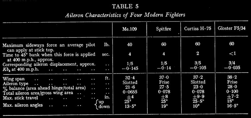
done more rapidly. " 5.2. Aileron
Forces and Times to Bank. – Aileron control at high speed is of considerable
topical interest. Rough measurements have recently been made9 of
the stick forces necessary to apply about 1/4-aileron at various speeds up to
400 m.p.h., together with the corresponding times to 45 deg. bank, on the
Curtiss H-75, Spitfire and Gloster F5/34, three modern singleseater fighters.
For comparison with this work, precisely similar tests were done on the
Me.109. The results are presented in Fig. 15 as
curves of stick force and times to 45 deg. bank plotted against indicated
airspeed Vi ; the previous Spitfire results are included in the diagram. At 400 m.p.h. the Me. 109 pilot, pushing
sideways with all his strength, can only apply about 1/5 aileron, thereby
banking 45 deg. in about 4 secs. ; on the Spitfire also, only 1/5 aileron can
be applied at 400 m.p.h., and again the time to 45 deg. bank is about 4 secs.
Both aircraft thus have their rolling manceuvrability at high speeds
seriously curtailed by aileron heaviness. The Spitfire ailerons do not feel
as " solid " at 400 m.p.h. as those of the Me. 109 ; this is
because there is rather more stretch in the aileron control circuit of the
Spitfire. An interesting point is that the maximum
sideways force a pilot can exert on the stick is about 60 lb. on the
Spitfire, but only about 40 lb. on the Me.109 ; the reason for this
difference is that the cockpit of the Me.109 is so cramped that a pilot
cannot bring his arm round into the position most favourable for applying a
large side force to the stick. The times to 45 deg. bank shown in Fig. 15
are of comparative value only, and do not indicate the variation of time to
bank with airspeed when a given amount of aileron is applied in a given time
; although the pilot attempted to apply the ailerons in about 1 sec. at all
speeds, he could not avoid applying them more slowly at the higher airspeeds,
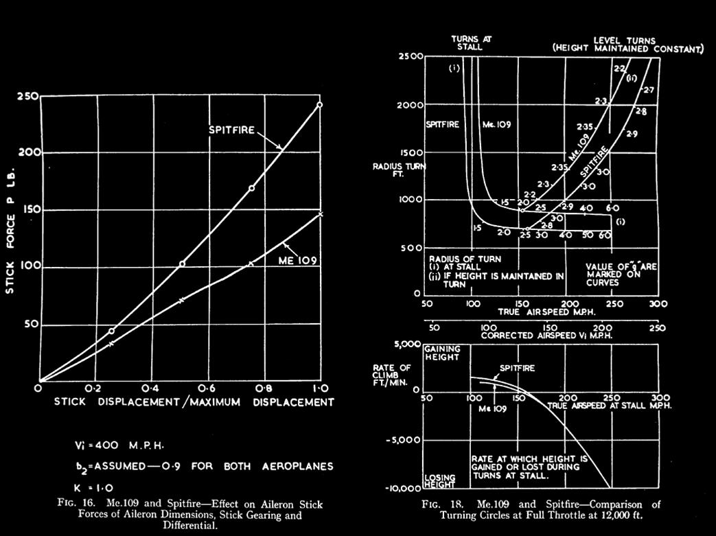
when the stick forces were very large. A method whereby values of the combined
balance and response factor of an individual aileron, Kb2, can be
deduced from the observed stick forces and displacements is given in Appendix
11, at the end of the report. At 400 m.p.h. Kb2 appears to be -
0.145 for the Me. 109 ailerons (slotted, 21.6 per cent. balance), and – 0.14
for the Spitfire ailerons (sharp nosed Frise, 27.5 per cent. balance). Comparative
data for the Me.109 and Spitfire ailerons are given in Table 2, and drawings
of the Me.109 ailerons in Fig. 10. To show the effect on aileron heaviness of
the geometry of the installation (aileron size, stick gearing, etc.), quite
apart from aileron balance, the variation of stick force with stick
displacement has been calculated for the Me.109 and Spitfire, assuming that
the ailerons of both aircraft have exactly the same value of Kb, (- 0.09, as
this was taken as standard in Ref. 8); the results are plotted in Fig. 16,
while details of the calculations are given in Table B of Appendix II.
Because of their smaller size the Me.109 ailerons should be only about half
as heavy as those of the Spitfire, other things being the same ; but this is
largely offset, especially for small aileron displacements, by the smaller
stick travel of the Me. 109, +/- 4 in. compared with +/- 8 in. on the
Spitfire. The following table summarises the most
important results emerging from these aileron tests and those described in
Ref. 9. |
|
This table brings out very forcibly the
wide differences, both in design and performance, between the aileron installations
of four typical modern single-seater fighters. Although ability to bank
quickly at high airspeeds is of cardinal importance in a fighter, aircraft
are still in service I whose ailerons are described by the pilots as "
almost immovable " at high speeds, and every effort should be and is
being made to avoid similar trouble on future designs. A comprehensive paper on aileron control
at high speed has recently been written by Gates and Irving11, and
general model research on the balancing of controls is in progress at the
National physical Laboratory. Steps are being taken to improve the Spitfire
ailerons, and an attempt is being made to frame a standard of aileron
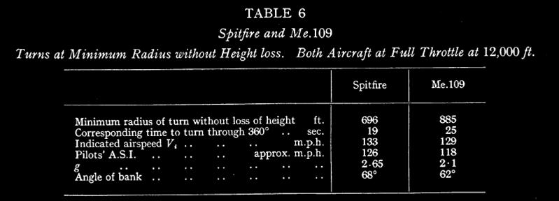
performance to which all future designs must comply. 5.3. Comparative Turning Performance of Me.109
and Spitfire. – During the dog-fights against the Hurricane and
Spitfire, it became apparent that our fighters could out-turn the Me.109 with
ease when flown by determined pilots. Since the minimum radius of turn
without height loss depends largely on stalling speed, and hence on wing
loading, the poor turning performance of the Me.109 may be ascribed to its
high wing loading, 32.2 lb./sq. ft. compared with 24.8 lb./sq. ft. on the
Spitfire. It was thought of interest to go into the matter a little more
deeply, and to calculate the relative performances of these aircraft in
circling flight, so that the sacrifice of turning performance entailed by the
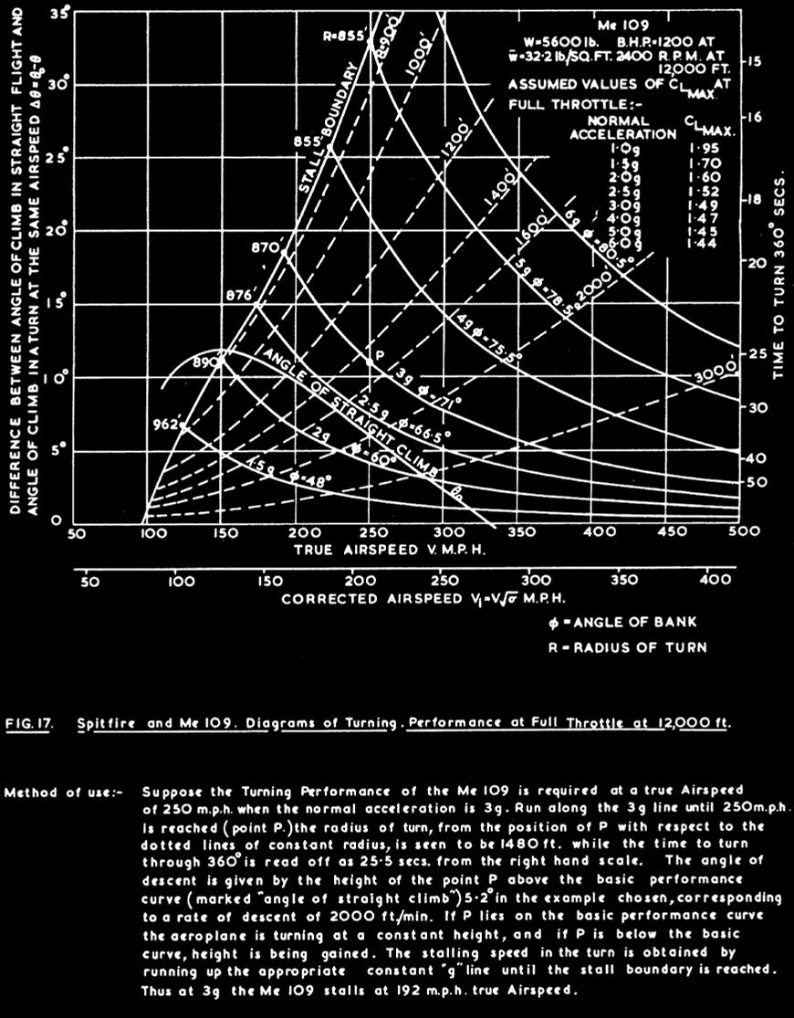
Me. 109's high wing loading could be assessed qualitatively. In a recent report on the dog-fight12
Gates gives an analysis whereby the performance of an aircraft in steady
spiral flight at full throttle can be estimated from its measured full
throttle performance in straight flight (partial climbs and top speed) ; the
analysis leads to a compact diagram from which the radius and time of turn,
and the corresponding rate of ascent or descent can be obtained at any given
airspeed and normal g. Such diagrams have been constructed for
the Spitfire and Me.109, and are given in Fig. 17, together with an
explanation of their use. The turning performance of the Hurricane is
probably little different from that of the Spitfire, these aircraft being
roughly similar in wing loading and level performance. The " stall
boundary " depends on an estimate of CL max at full throttle.
In the case of the Spitfire this has been measured in flight, while the
Me.109 figures were based on the Spitfire results; tables of the assumed
values of CL max are given in Fig. 17. CL max falls off
as g is increased, because the stalling speed increases as g
gets larger, thus lessening the slipstream effect. It will be seen that the minimum radius of
turn without height loss is obtained by flying as near the stall as possible
at a comparatively small g. For ease of comparison the radius of turn
has been plotted against speed for both aeroplanes in Fig. 18, (i) for turns
at the stall, and (ii) for turns without height loss. The advantage of the
Spitfire over the Me.109 at once becomes apparent, the minimum radius of turn
without loss of height being about 696 ft. on the Spitfire as against 885 ft.
on the Me.109. The characteristics of these turns are summarised in the
following table :- |
|
The turning performances of both
aircraft would undoubtedly be improved by use of a flap giving an appreciable
reduction of stalling speed thereby shifting the stall boundaries of Fig. 17
to the left. Calculations and flight tests are now being done on the use of
flaps for improving manceuvrability at low airspeeds and a report giving the
results of the investigation is in preparation.13 5.4.
Discussion. – The tests have shown that as a fighter the Me.
109 is in general inferior to the Hurricane or Spitfire. Its fighting
qualities, good and bad, may be briefly set out as follows : - Good points. (i) High top speed and excellent rate
of climb. (ii) Good control at low speeds. (iii) Gentle stall, even under g. (iv) Engine does not cut immediately under
negative g. Bad points. (i) Controls, particularly the
ailerons, far too heavy at high speeds. (ii) Owing to high wing loading, the
aeroplane stalls readily under g and has a poor turning circle. (iii) Aileron snatching occurs as the
slots open. (iv) Quick manoeuvres are difficult,
at high speed because of (i) above, at low speed because of (ii) and (iii). (v) Absence of a rudder trimmer,
curtailing ability to bank left at high speeds. (vi) Cockpit too cramped for comfort
when fighting. The gentle stall and good control
under g are of some importance, as they enable the pilot to get the most out
of the aircraft in a circling dog-fight by flying very near the stall. As
mentioned in section 5.1, the Me.109 pilot succeeded in keeping on the tail
of the Spitfire in many cases, despite the latter aircraft's superior turning
performance, because a number of the Spitfire pilots failed to tighten up the
turn sufficiently. If the stick is pulled back too far on the Spitfire in a
tight turn, the aircraft may stall rather violently, flick over on to its
back, and spin. Knowledge of this undoubtedly deters the pilot from
tightening his turn when being chased, particularly if he is not very
experienced. The most serious defect of the Me.
109 is its inability to roll fast in a high-speed dive because of its heavy
ailerons. Some of our own fighters are not free from this defect, the
Spitfire being about as bad as the Me.109 in this respect, and, as mentioned
in section 5.2, energetic action is now being taken to improve the aileron
control of our existing single-seater fighters. Measures are also being
considered to ensure that future designs will comply with an agreed high
standard of rolling manoeuvrability. Recent discussions with the Fighter
Command have made it clear that this provision of adequate lateral control at
high speed is at present the most pressing control problem of fighter design.
Next to this, the most important feature desired is ability to decelerate
quickly, so as to avoid overshooting when making a diving attack on a much
slower machine. To meet this requirement the design of a quickly operable
high-drag flap for single-seater fighters is being considered. Compared with the above, turning
performance in the circling slow speed dog-fight is now considered of minor
importance. The tactical situation may, however, change, and this aspect of
fighting manotuvrability should not be pushed too far into the background. As
shown in section 5.3, we have in the Spitfire and Hurricane, fighters
considerably superior to the Me.109 in slow speed turning performance.
Nevertheless, work on the effect of flaps on manoeuvrability at low speeds is
desirable, since the need for making our aircraft still better in this
respect may arise. 6.
Conclusions. – 6.1. Handling. – (i) Take-off is fairly
straightforward. The controls have an exceptionally good " feel "
and the aircraft is very stable during the approach glide, but the actual
touch down can be " tricky " until one gets used to the aircraft.
Taxying characteristics are good. (ii) Absence of a rudder trimmer is a
severe handicap at high speeds, since there is a large change of directional
trim with speed. Longitudinally the aircraft is too stable for a fighter. (iii) Good banked turns are possible
on ailerons or rudder alone. Sideslip produces a large nose-down pitching
moment. (iv) The stall is not violent and
there is no tendency to spin. CL max when gliding is 1.4 with
flaps up and 1.9 with flaps down. (v) No vibration or " snaking
" develops when the controls are displaced slightly and released in a
high-speed dive. (vi) Aileron snatching occurs as the
slots open. All three controls are far too heavy at high speeds. Aerobatics
are difficult. 6.2. Fighting Qualities.
– (i) In general the Me.109 is inferior
to the Humcane or Spitfire as a fighter because its manoeuvrability at high
speed is seriously curtailed by control heaviness, while its high wing loading causes it to
stall readily under g and results in a poor turning circle at low speeds. (ii) At 400 m.p.h. a pilot, pushing
sideways with all his strength, can only apply 1 / 5 aileron, the time to
bank 45 deg. being 4 secs. The Spitfire is as bad as the Me. 109 in this
respect. Kb2 for the Me.109 ailerons is – 0.145. (iii) The minimum radius of turn without
height loss is 885 ft. on the Me.109 compared with 696 ft. on the Spitfire. (iv) The cockpit is far too cramped
for comfort. APPENDIX I Pilots' Opinions on Cockpit Layout and
View 1.
Cockpit Layout. – A photograph of the cockpit interior
is given in Fig. 3. The two instruments with white dials at the top of the
dash-board are stick and rudder position indicators, fitted for the R.A.E.
tests ; a reflector sight normally occupies this space. It will be seen that
the German A.S.I. has been replaced by an English A.S.I. and English oxygen
equipment has been fitted. Apart from these alterations the layout is
standard. All three pilots gave their opinions
on cockpit layout, comfort and convenience, based on their experience during
the handling tests, and their views are summarised below. Cockpit
size. – The cockpit is unquestionably too cramped for
comfort. It is too narrow, the headroom is insufficient, and the seating
position is tiring. When wearing a seat-type parachute a pilot of normal size
finds that his head touches the hood roof. Noise. – With the
side windows open the noise in the cockpit is very considerable. It is
lessened by closing the side windows, but even then the cockpit is far
noisier at full throttle than I that of the Hurricane or Spitfire. Main Flying Controls . – The control column position is good,
and the slight offset of the grip is convenient (see Fig. 3). The position of
the rudder pedals makes for too reclining an attitude, Putting extra weight
on the small of the back. A bad feature is the absence of any fore-and-aft
adjustment of the rudder pedals. Trimming and Flap Controls. – These are
particularly well placed on the pilot's left. The flap gear is very good, for
it is easy to operate and, being manual, is not likely to go wrong. From the
Service point of view this system should be noted, as it might easily save
more serious accidents when the hydraulics are punctured. The juxtaposition
of the tailplane-adjusting wheel and the flap-control wheel was also considered
an excellent feature, as the wheels may be operated together with one hand
and the change of trim due to flaps thereby automatically corrected. Throttle. – The throttle
arrangements were described by one pilot as " marvellously simple, there
just being one lever with no gate or over-ride to worry about ". It may
be mentioned here that, while the pilots were not greatly impressed with the
Me.109 as an aircraft, the D.B.601 direct injection engine came in for very
favourable comment. The response to throttle opening is particularly good, it
is apparently impossible to choke the engine, and there is no tendency to
splutter and stop when the aircraft is subjected to a negative g by
suddenly pushing the stick forward. Airscrew Control. – This works well, no difficulty being
experienced during the tests. The pitch control lever would be better placed
alongside the throttle than on the dash-board. Undercarriage Control. – The undercarriage selector is free
from complication and cannot be criticised. The absence of an undercarriage
warning hooter seems strange to British pilots. Brakes. – These are
foot operated. They work well, but the standard Dunlop system operated from a
toggle on the stick is thought to provide a more sensitive control. Instrument Panel. – Except for the absence of a blind
flying panel, the instruments present are adequate and the grouping is good,
flying instruments being on the left and engine instruments on the right. The
absence of a gyro horizon is severely felt when flying in cloud. The
instruments are clear to read. No flying was done at night, but the lighting
arrangements appeared to be rather inadequate. Ancillary Equipment. – Guns, sights, wireless, etc., were
not tested. The wireless layout
appears to be well placed, and the machine gun and cannon firing
switches, mounted in the grip of the stick, come readily to hand. The
electrical panel on the lower right of the dash-board would be difficult to
use until the pilot became familiar with it, as the various press buttons
cannot readily be distinguished. An interesting feature is the
jettison arrangement for the Verey cartridges, designed to enable a pilot to
quickly jettison the cartridges before a forced landing in enemy territory,
so that he does not give away the signal of the day. 2.
View. – Fig. 4 shows the general windscreen layout. The
flat front panel is inclined at about 55 deg. to the horizontal when the
aircraft is in flying attitude ; the large corner panels are also flat, in
contrast to the curved panels of the Spitfire and Hurricane. The port corner
panel is divided into two parts vertically, and the forward portion hinges
inward about its leading edge, forming a direct vision opening about 9 in.
high by 3 in. wide at the top and 6 in. wide at the bottom; this opening is
inclined at 26 deg. to the direction of flight so that the width of forward
vision is about 2 in. The cockpit hood does not slide back.
It is hinged at the starboard side for entry and exit, and cannot thus be
opened in flight. Sliding windows are fitted, one in each side panel of the
hood. The hood jettisoning arrangements for emergency exit are interesting.
The hood is spring loaded, and on pushing the jettison lever the whole of the
hood and the wireless mast behind it are flung clear backwards. The view forward when taxying is very
bad, partly owing to the high ground attitude of the aircraft, and partly
because the hood cannot be slid back to enable the pilot to look round the
edge of the windscreen. When in flight, the view forward and
sideways is normal, being similar to the Hurricane; the windscreen framework
members are sufficiently narrow, and do not catch the pilot's eye nor create
blind spots. Sideways and rearwards the view is about the same as the
Spitfire and Hurricane, but the cramped position of the pilot in the cockpit
makes it difficult to look downward or upward to the rear, and the tailplane
can only be seen with an effort. The direct vision opening gives a
large field of view and is completely draught free at all speeds. A high
speed can thus be maintained in'bad weather conditions, whereas on the
Humcane or Spitfire the pilot must slide back the hood and look round the
edge of the windscreen to obtain a view-forward in rain or cloud, and can
only do this by flying at fairly low speed. The direct vision opening also
assists landing, as the high position of the nose obstructs the view forward
during the hold off, and the opening is in the correct position to give a
view of the ground. The direct vision opening obviously satisfies a very real
need, for the early Me.109s were not fitted with this device. The windscreen
panels are clear and free from distortion, and do not oil up in flight. The
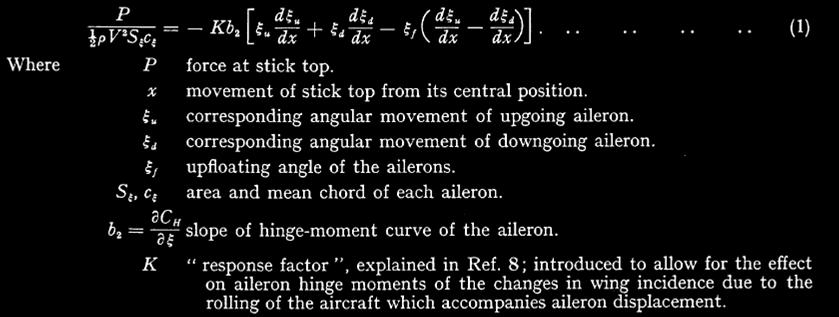
hood sliding panels are difficult to open, particularly at high speeds. APPENDIX II Analysis of Aileron Control Forces The following approximate formula may
be used to express the aileron stick force in terms of the geometry of the
aileron system and the balance characteristics of the individual aileron ;
the analysis whereby this equation is derived is set out fully in Ref. 8. |
|
The above equatation enables the
combined balance and response factor Kb2 to be evaluated from the stick force measurements
described in section 5.2 and plotted out in Fig. 15. The values of Kb2
so obtained are given below, similiar figures for the Spitfire ailerons8
are included for comparison.
In order to show the effect on
aileron control forces of the geometry of the aileron installations, quite
apart from the aerodynamic balance of the individual ailerons, control forces
at 400 m.p.h. have been calculated from equation (1) for the Me.109 and
Spitfire, assuming a uniform value of – 0.09 for Kb2 for the
ailerons of both aircraft. These calculated stick forces are
plotted against stick displacement in Fig. 16, while Table B below gives
details of the calculation; a study of Table B enables the relative effects
of size, stick gearing, differential, etc., to be clearly seen. |
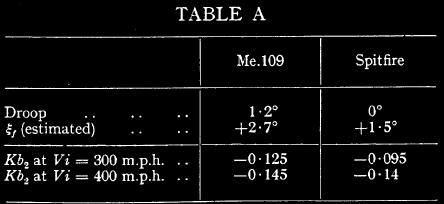
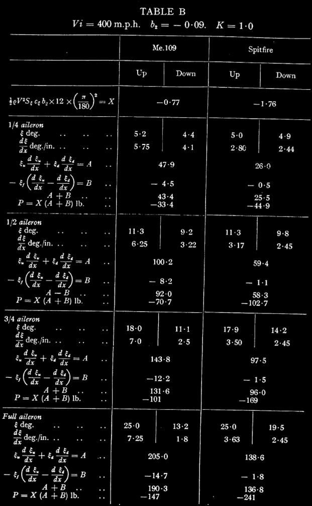
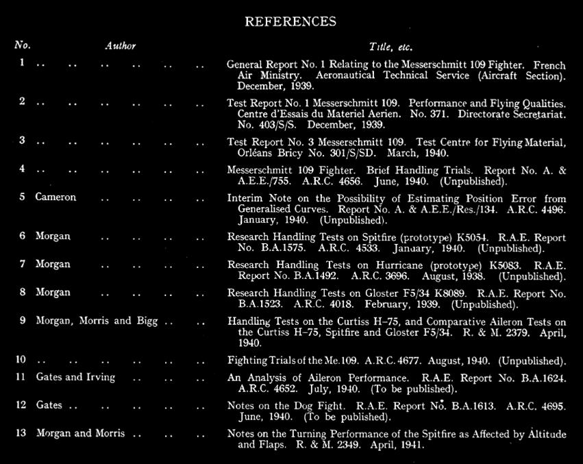
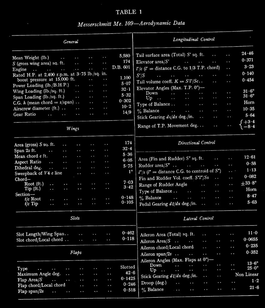
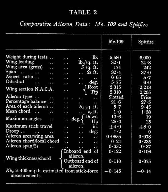
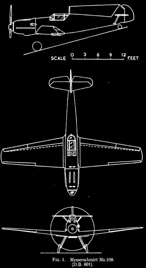
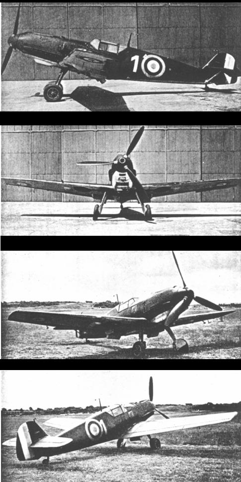
FIG. 2.
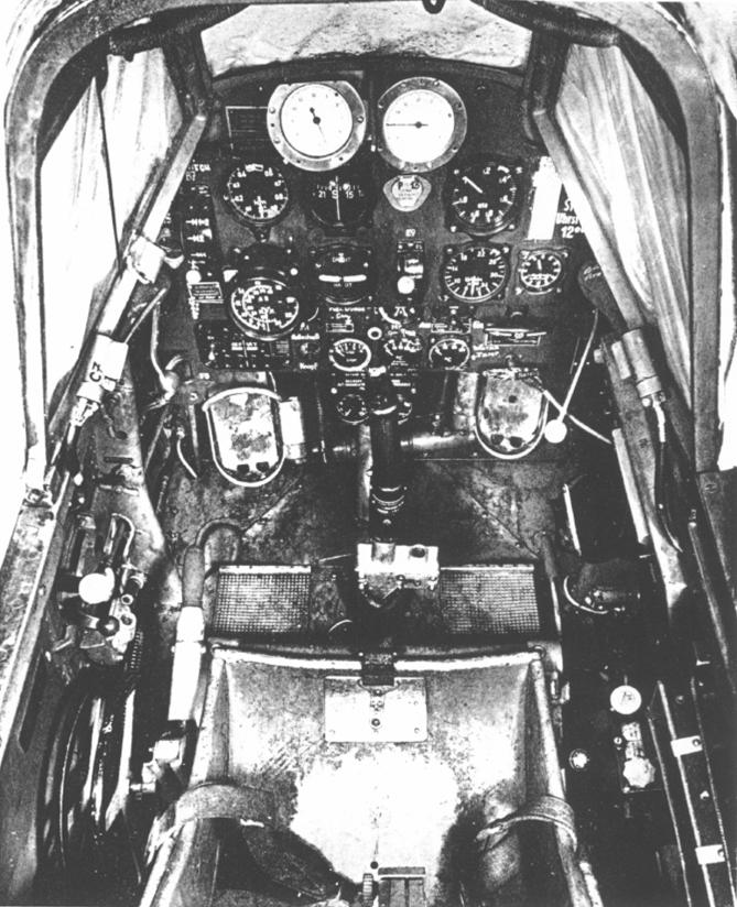
FIG. 3. Cocpit
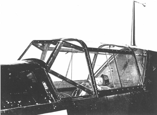
FIG. 4. Windscreen
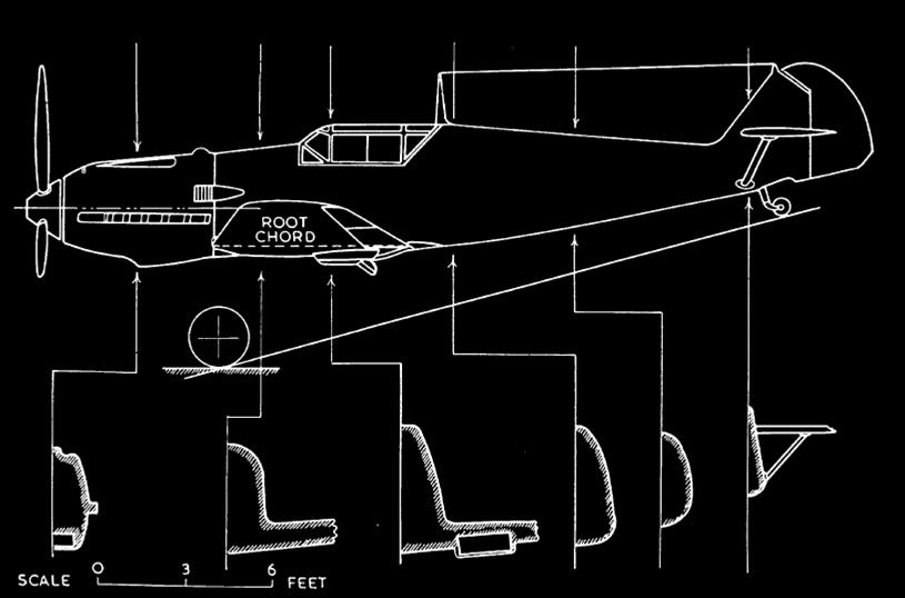
FIG. 5. Fuselage sections
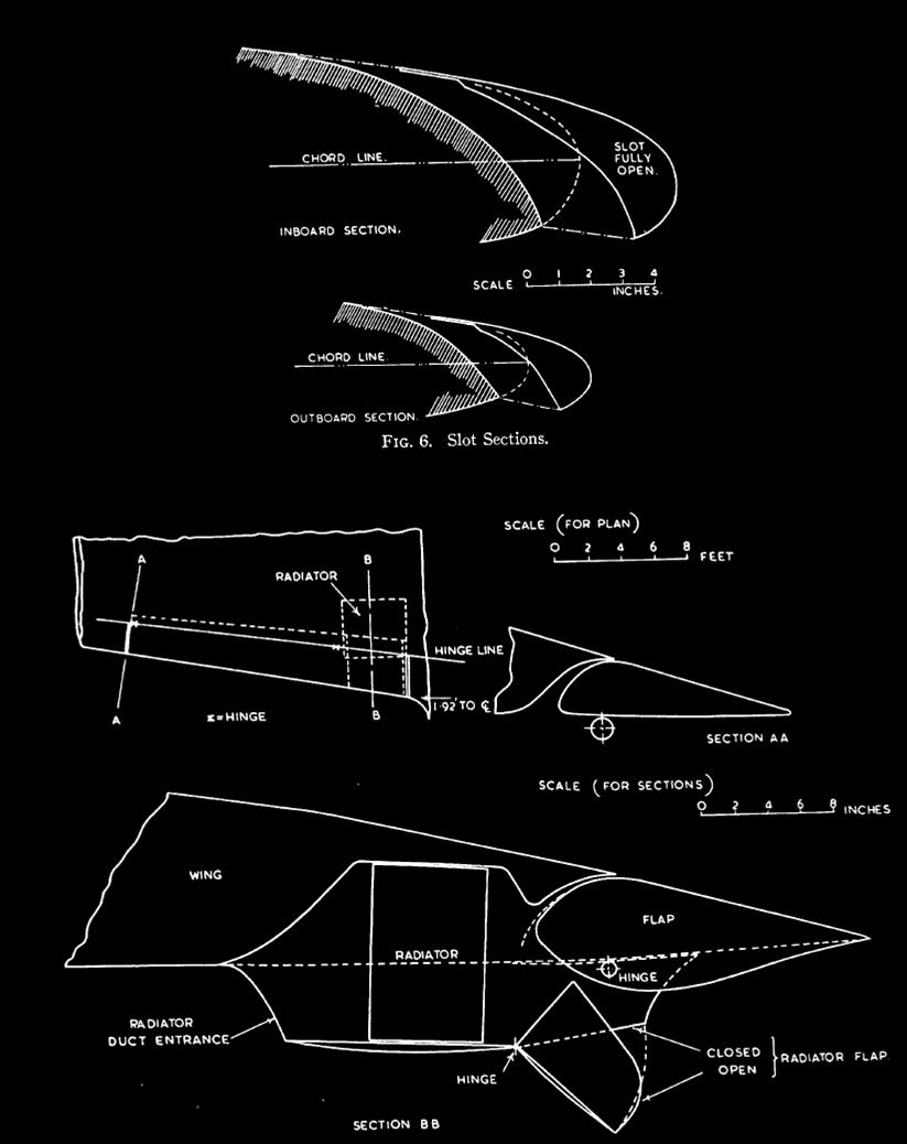
FIG. 7. Plan and sections of flap

Sources and References:
Messerschmitt Me. 109 Handling and Manoeuvrability Tests BY M. B.
MORGAN, M.A. and D. E. MORRIS, B.SC. MINISTRY OF SUPPLY Reports and
Memoranda No. 2361 .September 1940*
Last updated 19 July 2008.
Work in progress.
All rights reserved.
email at : kurfurst@atw.hu
Total Site Page loads :